
 Business License

Gold CIL vs Gold CIP: Which Circuit Fits Your Ore
The gold cil vs cip question comes up in nearly every cyanidation project review, and the answer is rarely obvious from the head grade alone. Both routes dissolve gold in cyanide and both recover it onto activated carbon, so they look similar on a flowsheet sketch. The real difference sits in where adsorption happens relative to leaching, and that single detail reshapes tank sizing, carbon management and recovery.
This guide compares the two circuits stage by stage. It covers the mechanism behind each route, the ore types that favour one or the other, published operating ranges for time, carbon concentration and gold recovery, and the capital and operating gaps that decide real projects. It closes with a selection checklist and a set of practical questions.
1. What Separates Gold CIL vs CIP: The Core Mechanism
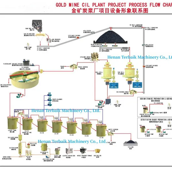
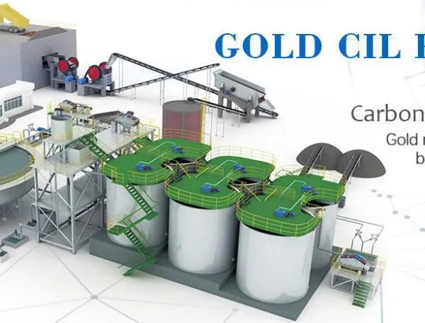
In a CIL circuit, cyanide leaching and carbon adsorption happen in the same vessel. Activated carbon is added directly to the leach tanks, so gold dissolves out of the ore and loads onto the carbon while the pulp is still being agitated. The two reactions compete for the same dissolved gold ion, and the tank train is designed around that competition.
In a CIP circuit, the two steps are split. Pulp first passes through dedicated leach tanks with no carbon present, so the gold has time to dissolve fully into solution. Only after leaching is complete does the pulp move into adsorption tanks, where carbon is added counter-current to the slurry flow to collect the dissolved gold.
That difference decides the carbon adsorption route you design for, because the carbon adsorption route you choose places different demands on agitation, residence time and carbon transfer. In CIL, the leach kinetics and the adsorption kinetics have to work in harmony from the first tank. In CIP, leach kinetics are settled before carbon ever enters the picture, which makes troubleshooting simpler but adds a separate tank section.
Neither route is newer or better in general terms. CIL usually needs fewer tanks for the same duty because adsorption overlaps leaching, while CIP usually gives cleaner kinetic data because the two stages can be tuned independently. The right answer to gold cil vs cip depends on the ore, the clay content and the capital available.
2. Ore Types That Decide the Gold Leaching Circuit Selection
Gold leaching circuit selection starts with the physical and chemical character of the ore. High-clay and high-slime ores behave very differently from clean, sandy free-milling ores, and that difference often points to one route before any other test is run. Preg-robbing carbonaceous ore adds a further complication that no gold leaching circuit selection can simply ignore.
Ores with heavy clay and high fines usually favour CIL. The carbon is already in contact with the pulp throughout leach, so there is no extra transfer step to clog, and fewer tanks mean less chance of sanding or short-circuiting. Agitation in a single combined train also keeps viscous pulps moving more reliably than a long sequence of separate leach and adsorption vessels.
Coarse and fast-settling ores tend to favour CIP, because the adsorption tanks can run at higher pulp density and the counter-current carbon movement handles settled grit more predictably. Where the ore settles quickly, a clean leach section also lets operators sample solution chemistry without carbon interference.
Carbonaceous ore that preg-robs gold is the awkward case, and it usually needs a flotation or other pre-treatment step ahead of either circuit. Flotation can float much of the active carbon away before cyanidation, which protects the recovery you would otherwise lose to native preg-robbing matter, and this pre-treatment is often the single most valuable decision in the whole flowsheet.
3. Process Metrics Compared Across Both Routes
The operating differences between the two routes show up clearly in a small set of measured values. Leaching time, carbon concentration, carbon particle size, the number of stages and the resulting gold recovery all shift depending on where adsorption sits. Cyanide consumption and carbon attrition follow the same logic, so the two circuits can be compared on a like-for-like basis once those figures are known.
Because CIL overlaps leaching and adsorption, total residence time is usually shorter than in CIP, and the tank train is often smaller. Carbon concentration is typically lower and more evenly spread in CIL, because carbon is present from the start rather than introduced at the back end. CIP, by contrast, usually runs a higher carbon concentration in fewer, well-staged adsorption tanks. That contrast is the heart of any gold cil vs cip comparison on paper.
The table below summarises the ranges that most scoping studies use for gold cil vs cip comparisons. The values are typical planning figures, not guarantees, and each deposit should confirm them with its own gold leaching circuit selection test work.
| Parameter | Gold CIL | Gold CIP |
|---|---|---|
| Where adsorption occurs | Same tanks as leaching | Dedicated tanks after leaching |
| Typical leach and adsorption time | Around 18 to 30 hours total | Usually 24 to 40 hours split between stages |
| Carbon concentration | Roughly 10 to 25 g/L in each tank | Typically 15 to 40 g/L in adsorption tanks |
| Carbon particle size | Usually 6 to 16 mesh | Typically 6 to 16 mesh |
| Number of stages | Usually 5 to 8 combined tanks | Around 4 to 6 leach plus 4 to 6 adsorption |
| Typical gold recovery | Roughly 92 to 97 percent of leachable gold | Around 90 to 96 percent of leachable gold |
| Cyanide consumption | Typically 0.5 to 1.5 kg/t | Usually similar, sometimes lower |
| Carbon attrition | Usually higher due to longer pulp contact | Typically lower with gentler transfer |
Carbon particle size is closely matched between the routes, because both rely on the same granular activated carbon to adsorb the dissolved gold complex. What changes is how long that carbon sits in abrasive pulp, and that contact time drives the attrition figure quoted in the final row.
4. Capital, Operating and Maintenance Differences
Capital cost usually favours CIL on a greenfield site, because one combined train of tanks replaces two separate sections. Fewer tanks mean less steel, less piping and a smaller footprint, and the overlap between leaching and adsorption often trims total residence time as well. For a given throughput, gold cil vs cip capital usually favours CIL and lowers the installed cost of the leach and adsorption area.
CIP spreads the duty across more tanks, so installed cost is typically higher, but the layout can be easier to expand later. Adding an adsorption tank to a CIP train is a more contained change than lengthening a combined CIL train, which matters when a project is built in stages, and the choice of carbon adsorption route often turns on exactly this flexibility.
Operating cost differences are more subtle and depend heavily on the ore. Both routes consume cyanide, lime and activated carbon, and the dominant cost is usually cyanide followed by carbon. CIL tends to lose more carbon to attrition because the granules spend longer in abrasive pulp, so carbon make-up can be slightly higher. Amill Machinery Equipment factors carbon loss and cyanide consumption into operating estimates during process design, because these two lines often decide whether a marginal project clears its hurdle.
Maintenance and control philosophy also differ. The carbon adsorption route you select demands stable agitation and careful pH control across every tank, since a stalled tank affects both leaching and adsorption at once. CIP gives operators a cleaner split between the two duties, which can simplify fault-finding and operator training even if the tank count is higher.
5. A Practical Selection Checklist
Use the checklist below to narrow the two routes before detailed engineering begins. Each line should be answered from test data rather than assumption, and the list is written so that a scoping study can be completed in days rather than weeks. The final decision should rest on measured recovery and cost, not on habit.
First, confirm the gold leachability and the leach kinetics from bottle roll tests, because neither circuit can recover gold that will not dissolve. Second, measure preg-robbing behaviour directly, since native carbon can steal dissolved gold from either route and may force a pre-treatment step. Third, assess clay and slime content, which pushes the gold leaching circuit selection toward CIL for sticky pulps.
Fourth, note whether the ore settles quickly or slowly, because fast-settling material is usually easier to handle in a CIP adsorption train. Fifth, compare the tank count and footprint for each option against the site layout and the expansion plan. Sixth, check cyanide and carbon consumption side by side, since the incremental cost difference often decides the tie.
The table below turns those points into a compact decision guide. It is meant to be a starting filter, not a substitute for a full metallurgical study.
| Condition | Leaning Toward CIL | Leaning Toward CIP |
|---|---|---|
| Clay and slime content | High, sticky pulp | Low, clean pulp |
| Ore settling behaviour | Slow or non-settling | Fast-settling and gritty |
| Carbon pre-treatment need | Lower if carbon already separated | Lower on clean oxide ore |
| Capital budget | Typically lower | Usually higher |
| Expansion flexibility | Sometimes limited | Usually easier to add tanks |
| Control simplicity | Integrated but interdependent | Cleaner stage separation |
Not long ago, a West African oxide deposit carried around 1.9 g/t gold with roughly 28 percent clay and high fines. Bottle roll tests reached about 95 percent extraction in roughly 22 hours, and the clay behaved so badly that a CIP transfer line kept plugging during pilot trials. The project switched to a CIL train of six tanks at roughly 1,200 tpd, held a carbon concentration near 18 g/L and finished commissioning at about 94 percent recovery. Carbon attrition ran slightly above the pilot estimate, yet the reduced clay handling offset the extra carbon cost, and the operating team reported fewer stoppages than on a comparable CIP circuit.
A second case points the other way, and it involved a clean, fast-settling oxide ore some time ago. The deposit ran about 2.6 g/t gold with low clay, so a CIP circuit at approximately 800 tpd reached roughly 95 percent recovery with low carbon loss.
5.1 Matching the Circuit to Downstream Refining
Once the choice is made, the loaded carbon moves through elution, electrowinning and refining regardless of which route produced it. That downstream section is shared, so it rarely changes the CIL or CIP decision directly. What it does change is the carbon quality target, because higher attrition means more fine carbon that must be screened out before elution.
For combined plants, the leach and adsorption circuit is usually fed by the same grinding section that serves flotation or gravity equipment. Amill Machinery Equipment builds crushing, grinding, gravity, flotation and cyanidation lines as one coordinated plant, which keeps the feed size consistent across every downstream stage. That consistency matters more than any single equipment choice, because a leach train fed with the wrong size distribution will struggle no matter how well it is designed.
6. FAQ: Gold CIL vs Gold CIP
The questions below cover the points that come up most often when owners and metallurgists compare the two circuits. The answers assume typical oxide or free-milling ore, so confirm every figure against your own test work before committing capital to a flowsheet.
6.1 Which route is better for gold cil vs cip on a clay-rich ore?
For clay-rich ore, CIL usually wins because carbon sits in the same agitated vessel as the pulp and there is no separate transfer stage to plug. Sticky, high-slime pulps move more reliably through one combined train of tanks than through a long sequence of separate leach and adsorption vessels. Clay also tends to settle poorly, so a CIP layout can suffer short-circuiting and sanding that CIL avoids more easily.
Test both routes on the same composite before deciding, because clay behaviour varies widely between deposits. Confirm the gold leaching circuit selection with a pilot run whenever the clay content is high, since bench results often understate the handling difficulty.
6.2 How much does the carbon adsorption route affect recovery?
The carbon adsorption route influences recovery mainly through contact time and carbon activity, not through the chemistry of adsorption itself. Because CIL overlaps leaching and adsorption, dissolved gold is captured quickly and less is lost to the tailings, which often pushes recovery toward the upper end of the usual range. CIP captures gold just as efficiently once the pulp reaches the adsorption tanks, provided the leach stage has already dissolved it.
In practice, both routes land within a few percentage points of each other on the same ore. The gap widens only when preg-robbing carbon, high clay or poor agitation upsets one circuit more than the other.
6.3 What are typical carbon concentration and particle size values?
Carbon concentration is usually held around 10 to 25 g/L per tank in CIL and roughly 15 to 40 g/L in CIP adsorption tanks, measured as grams of carbon per litre of pulp. Particle size is closely matched at about 6 to 16 mesh in both routes, because the carbon granules must be coarse enough to screen back out of the slurry. Finer carbon adsorbs faster but is lost more readily to attrition.
Operators monitor carbon activity and make-up rate together, since spent carbon loads more slowly and forces a higher inventory. These two figures, concentration and particle size, drive most of the day-to-day cost difference between the routes.
6.4 How long does each circuit take to reach full recovery?
Total residence time usually falls around 18 to 30 hours in CIL, because leaching and adsorption proceed together in the same tanks. CIP typically needs roughly 24 to 40 hours split between its leach section and its adsorption section, since the two duties run in sequence rather than in parallel. Longer times raise tank volume and capital cost, so designers aim for the shortest time that still meets the recovery target.
The right figure depends on leach kinetics, which vary with ore mineralogy, grind size and cyanide strength. Bottle roll tests give the first estimate, and pilot runs confirm it before tank sizing is fixed.
6.5 Can CIL and CIP be combined in one plant?
A combined layout is possible but uncommon in practice, because the two routes solve the same problem in different ways and rarely need to run side by side. Where a plant treats two ore zones, a split feed with one circuit per zone can make sense, and the shared crushing, grinding and refining sections limit the extra capital. Amill Machinery Equipment designs the front end so either circuit can be fed from the same grinding line, and our team settles the choice with test work rather than convention.
A single, well-tuned circuit almost always beats two half-loaded ones, so reserve the combined approach for genuinely mixed ore bodies.
Recently Posted
-
What Is a Lead Zinc Flotation Plant? A Complete Overview
October 16, 2026A lead zinc flotation plant definition is the starting point of this overview, and the term describes a mineral processing install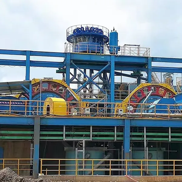 Read More
 -
Screening Plants for Indonesian Nickel Laterite
October 16, 2026Indonesia sits at the center of the global nickel supply chain, and most of that output comes from laterite ore mined in Sulawesi,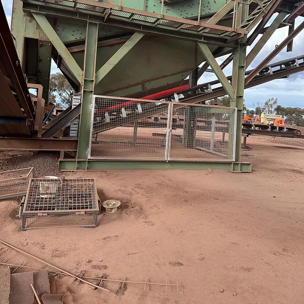 Read More
 -
Quality Control in Flotation Cell Manufacturing
October 16, 2026A flotation cell looks simple from the outside: a tank, a rotor, a drive and an air pipe. Inside, it is a pressure vessel for pulp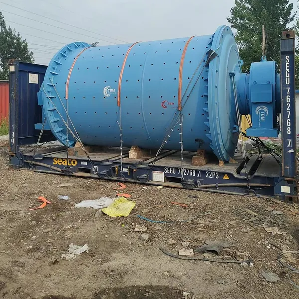 Read More
 -
Grinding Circuit Specifications for Ore Beneficiation
October 15, 2026Grinding circuit specifications are the backbone of every mineral processing flowsheet, because the mill sets the size distributio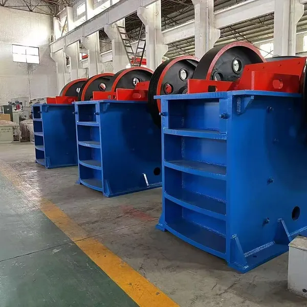 Read More

Contact Us
Recommended Products
-
 200 Tpd High Recovery Lead-zinc Ore Flotation PlantUS$ 15000MOQ: 1 Combo
 -
China Hot Sale 50-600 Tpd Copper Ore Flotation Plant With Rich ExperienceUS$ 20000MOQ: 1 Combo
-
Copper Ore Processing Flotation PlantUS$ 25000MOQ: 1 Combo
-
Hard Rock Gold Processing CIL PlantNegotiableMOQ: 1 Set
-
Gold Ore CIL Processing PlantNegotiableMOQ: 1 Set
-
Gold CIL Plant With One Stop Gold Processing EquipmentNegotiableMOQ: 1 Set
-
Gold CIP Plant for Efficient Carbon-in-Pulp Gold RecoveryNegotiableMOQ: 1 Set
-
Gold CIL Plant Engineering Design Service Metallurgical Process OptimizationNegotiableMOQ: 1 Set
-
Gold Extraction CIL Processing Plant High Efficiency Carbon Leach Gold ProcessUS$ 5000MOQ: 1 Set
-
Copper Ore Flotation Beneficiation ProcessNegotiableMOQ: 1 Set
-
Copper Flotation Plant With Advanced Flotation Machine, Customized Mineral Processing Solution, Stable Copper RecoveryNegotiableMOQ: 1 Set
-
Mobile Crusher | Crawler and Wheeled Crushing PlantNegotiableMOQ: 1 Set
-
Jaw Crusher Price ,big Stone Jaw CrusherUS$ 25000MOQ: 1 Set
-
100- 500 Tpd Gold CIL CIP Processing PlantUS$ 25000MOQ: 1 Set
-
River Stone Granite Stone Crusher PlantUS$ 25000MOQ: 1 Combo
-
500 Tpd Rotary Kiln Gypsum Production Line for Sale in AfricaUS$ 25000MOQ: 1 Combo
-
Gold CIL CIP Extraction Plant 100-300 TPD Activated Carbon Leaching 95% Recovery Rate EPC ProjectNegotiableMOQ: 1 Set
-
Gold CIL CIP Leaching Plant 100-500 TPD Activated Carbon Leaching High Efficiency EPC ProjectNegotiableMOQ: 1 Set
-
High Efficiency Lead Zinc Flotation Plant for Ore RecoveryNegotiableMOQ: 1 Set
-
Lead Zinc Flotation Processing Plant for Polymetallic OreNegotiableMOQ: 1 Set