
 Business License

What Is a Gold CIL Plant? Definition and Core Components
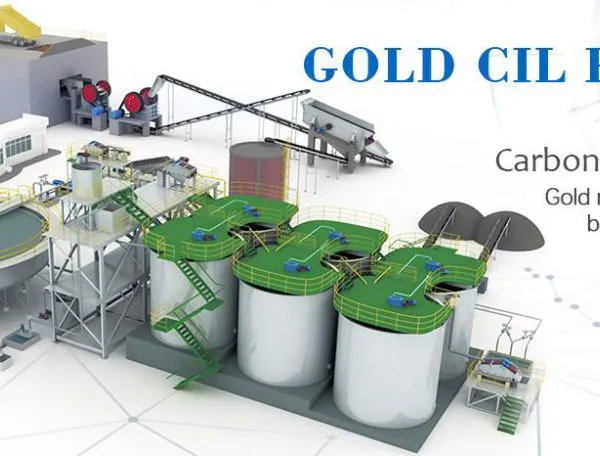
A gold CIL plant definition is simple to state. It is a mineral processing facility in which finely ground gold ore is leached in a cyanide solution while activated carbon is suspended in the same tanks, so that dissolved gold is adsorbed onto the carbon as soon as it enters solution. The carbon is then moved forward through a series of tanks against the flow of pulp, lifted out at the head end, and stripped of its gold in a separate elution circuit. That single idea, leaching and adsorption happening together, is what separates this arrangement from a conventional leach and separate adsorption flowsheet.
This article builds on that gold cil plant definition and explains the gold carbon in leach process from crushing through to smelting. It covers the structure of the gold cil leaching tank, how carbon is kept in suspension and moved in reverse, how loaded carbon is recovered, and which operating numbers engineers watch. Read this way, a gold cil plant definition becomes a map of the whole flowsheet rather than a single sentence. It is aimed at project owners and metallurgists who need a clear picture before they commit to a flowsheet.
1. Definition of a Gold CIL Plant and Its Core Sections
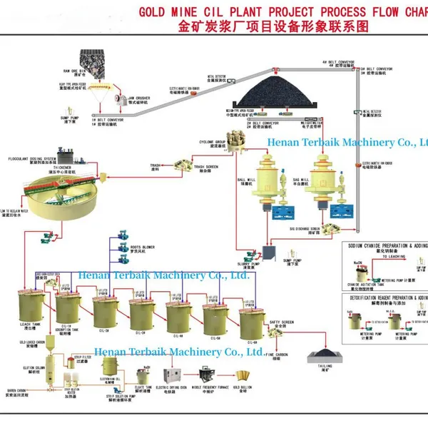
A complete definition has to cover both the equipment train and the sequence of operations. Physically, the plant includes crushing, grinding and classification, optional pre-treatment, a train of leach tanks, carbon handling, elution and electrowinning, smelting, and tailings treatment. Functionally, it is a continuous process that dissolves gold from ore and captures it onto carbon in one connected circuit.
The word plant also implies integration, which is why any practical gold cil plant definition must include the linking equipment between stages. Each stage feeds the next, so a bottleneck anywhere limits the whole line, and designers therefore treat the circuit as one connected system rather than a collection of independent machines. Section sizing is always done together, from the primary crusher to the tailings thickener.
The table below lists the main sections of a typical plant and the role each one plays. Capacities are normally quoted in tonnes per day of fresh feed, and they scale with the size of the deposit being worked.
| Section | Main equipment | Purpose |
|---|---|---|
| Crushing | Jaw and cone crushers | Reduce run-of-mine ore to a transportable size |
| Grinding | SAG or ball mill, cyclones | Liberate gold and prepare fine feed |
| Pre-treatment | Flotation or oxidation unit | Remove sulphides that consume cyanide |
| Leaching | Leaching tanks in series | Dissolve gold and adsorb it onto carbon |
| Recovery | Elution and electrowinning | Strip gold from carbon and plate it out |
| Finishing | Furnace and tailings plant | Produce doré and manage residues |
Each section has its own control philosophy, yet they only work when tuned together. A plant that optimises grinding in isolation usually pays for it in leach performance.
2. Crushing, Grinding and Pre-Treatment Before Leaching
The gold carbon in leach process begins with size reduction. Run-of-mine ore is crushed and then ground, normally in a ball mill circuit closed by hydrocyclones, until the gold is liberated from the host rock. Grind size is one of the most important choices in the whole flowsheet, because it sets the balance between gold liberation and the amount of very fine material that can blind the carbon.
Most leach circuits run a primary grind around P80 of 75 microns, though coarse gold ores sometimes call for a coarser product while refractory ores often need a finer one. Close circuiting with cyclones keeps the product consistent, and a gravity or flash flotation step is sometimes inserted ahead of leaching to recover coarse free gold early.
Pre-treatment matters when the ore carries sulphides or preg-robbing carbon. Sulphides consume cyanide and oxygen, so flotation is often used to reject a sulphide concentrate before leaching, and pressure oxidation or bio-oxidation may be applied where the gold is locked inside sulphide grains. Preg-robbing carbon in the ore is a separate problem, because it adsorbs dissolved gold before the plant carbon can, and it is managed by blinding the natural carbon or by treating it in a pre-oxidation stage.
The table below shows typical feed parameters for a leach circuit, together with the effect each one has on the gold carbon in leach process. Values are indicative and should be confirmed by testwork on the actual ore.
| Feed parameter | Typical value | Effect on leaching |
|---|---|---|
| Primary grind size | around P80 75 microns | Controls gold liberation and carbon blinding |
| Pulp density | roughly 40 to 50 percent solids | Affects retention time and mixing |
| Sulphide content | varies with deposit | Higher levels raise cyanide demand |
| Preg-robbing carbon | usually tested in the lab | Can remove gold before plant carbon does |
| Feed gold grade | typically 1 to 5 g/t | Sets the target carbon loading |
Because ore bodies change with depth, many operations move from oxide to sulphide as mining advances. Designers often allow for this transition by leaving room to add a pre-treatment stage later without rebuilding the leach train.
3. Leaching Tanks, Residence Time and Carbon in Suspension
The gold cil leaching tank is the centre of the plant and the part most often misunderstood. Each gold cil leaching tank is a large agitated vessel, usually fitted with a draft tube and an axial impeller, designed to keep solids in suspension and carbon evenly distributed through the pulp. Tanks are arranged in series, normally five to eight of them, so that the pulp moves stage by stage while the carbon travels in the opposite direction.
Residence time is the key sizing figure. Total leach time across the train is usually around 18 to 30 hours for a typical oxide ore, divided across the individual tanks. Too little time leaves gold undissolved, while too much time adds tank volume and capital cost without a matching gain. The train is therefore sized from kinetic testwork rather than from a standard rule.
Conditions inside the tanks are held in a narrow band. pH is maintained at roughly 10 to 11 with lime so that hydrogen cyanide gas does not form, cyanide concentration is usually kept around 100 to 500 parts per million, and dissolved oxygen is sustained by air or oxygen sparging because gold dissolution needs oxygen as well as cyanide. Carbon is held at a concentration of roughly 10 to 25 grams per litre of pulp, which gives enough surface area for fast adsorption without overloading the agitators.
Carbon quality matters as much as quantity, and so does the design of each gold cil leaching tank. Fresh coconut shell carbon with a size around 1.2 to 3.4 millimetres is the usual choice, because it resists attrition and carries a high adsorption capacity for gold. Loaded carbon typically reaches a loading of roughly 2,000 to 6,000 grams of gold per tonne of carbon before it is advanced to elution.
- Keep pulp in suspension so that carbon stays distributed.
- Hold pH near 10 to 11 to suppress hydrogen cyanide.
- Maintain cyanide in solution rather than dosing to a fixed rate.
- Supply oxygen continuously for gold dissolution.
- Screen carbon at each stage to return fine material and prevent losses.
Because adsorption and leaching happen in the same vessel, the circuit is more compact than a leach and separate adsorption design, and it handles ores that adsorb gold slowly with less risk of losses to the tailings.
4. Carbon Movement, Elution, Electrowinning and Smelting
Carbon flow is counter-current, which means fresh carbon is added at the last tank and loaded carbon is withdrawn from the first. This arrangement keeps the pulp with the richest gold in contact with the freshest carbon, so the concentration gradient favours adsorption throughout the train. The carbon is moved between tanks by air lifts or pumps and screened at each stage so that broken particles are removed.
Loaded carbon then moves to elution, where gold is stripped back into solution. The common AARL process uses hot caustic cyanide solution at roughly 90 to 120 degrees Celsius under mild pressure, and it typically recovers the adsorbed gold within a few hours. Less reagent is needed because the carbon leaves the elution column with very little gold remaining on it, and it is then regenerated in a kiln and returned to the leach train.
The eluate, which is the gold-bearing solution from elution, goes to electrowinning. Current is passed through the solution and gold plates onto steel wool cathodes, from which it is washed off and collected. The resulting sludge is dried, mixed with fluxes and smelted in a furnace to produce doré bars that are shipped to a refinery. Overall gold recovery for a well-run plant is usually in the range of 88 to 95 percent, though refractory ores sit lower.
The table below summarises the main operating parameters across the recovery section. These are planning ranges, and each deposit settles on its own numbers after commissioning.
| Parameter | Typical value | Stage |
|---|---|---|
| Leach time | around 18 to 30 hours | Leach train |
| Cyanide concentration | roughly 100 to 500 ppm | Leach train |
| pH | usually 10 to 11 | Leach train |
| Carbon concentration | typically 10 to 25 g/L | Leach train |
| Carbon particle size | around 1.2 to 3.4 mm | All stages |
| Elution temperature | roughly 90 to 120 C | Elution |
| Overall gold recovery | usually 88 to 95 percent | Whole plant |
Control systems tie the recovery section together. Pulp level, carbon advance rate, cyanide set point and elution cycle time are the main levers, and modern plants adjust them continuously from assay data. That kind of control keeps the circuit responsive as ore conditions shift.
5. Tailings Treatment and Cyanide Management in the Gold Carbon in Leach Process
Pulp leaving the last leach tank still carries residual cyanide and fine solids, so it is usually passed through a cyanide destruction step before it reports to the tailings storage facility. The common approach oxidises cyanide with reagents such as ferrous sulphate, hydrogen peroxide or a sulphite and air combination, and it reduces the weak acid dissociable cyanide to a low residual level.
Water recovery runs alongside destruction. Tailings are thickened so that process water can be returned to the plant, and the thickened underflow is pumped to the storage facility. A well-designed pond separates solids from the return water and is lined and monitored, so that seepage and dust are both controlled.
Monitoring is continuous, and the company treats it as part of the process rather than a reporting duty. Cyanide levels in the tailings and in the return water are checked on every shift, and the destruction reagent dose is trimmed to match. In the gold carbon in leach process, tailings management is where most of the environmental control effort sits, and it is also where reagent savings are found, because recycled water carries residual cyanide back to the leach train.
For owners scoping a new project, working with a supplier who covers the whole chain is a practical advantage. Henan Amill Machinery Equipment Co Ltd handles process design, equipment selection, manufacturing and commissioning guidance, and Amill Machinery serves mining clients across South America, Africa, Southeast Asia and the Middle East. Amill Machinery Equipment builds complete mineral processing plants rather than single machines, which helps keep the flowsheet consistent from crusher to tailings.
A brief example from a few years ago shows how the numbers settle in practice. A 600 tpd plant treating an oxide ore with a head grade near 1.8 grams per tonne ran a six tank train with about 22 hours of leach time and carbon held at roughly 14 grams per litre. Cyanide consumption came in near 0.8 kilograms per tonne, and recovery settled at about 92 percent.
A second case, not long ago, involved a plant that was losing gold to a preg-robbing ore blend. Our team tested the blend at bench scale first, then added a short pre-oxidation step ahead of the leach train, which lifted recovery from roughly 85 percent to about 90 percent on the blended feed.
Understanding the definition is therefore a matter of following the gold, not just naming the equipment. Ore is ground, leached and adsorbed in one tank train, the carbon carries the gold forward against the pulp, and elution, electrowinning and smelting deliver the metal. A plant designed around those links, rather than around individual machines, is the one that holds its recovery.
6. FAQ
6.1 What is the clearest gold CIL plant definition?
The clearest gold CIL plant definition is this: a plant that leaches gold ore in cyanide solution and adsorbs the dissolved gold onto activated carbon inside the same tanks. Because adsorption follows leaching immediately, the gold does not travel far in solution before it is captured, which limits losses and keeps the circuit compact. Everything else in the facility, from crushing and grinding upstream to elution, electrowinning and tailings treatment downstream, exists to support that combined step, so the definition really describes one connected process rather than a single machine.
6.2 What happens inside a gold cil leaching tank?
Inside a gold cil leaching tank, an agitator with a draft tube keeps the pulp in suspension while activated carbon is distributed evenly through the slurry. Cyanide dissolves the gold and the carbon adsorbs it at the same time, and oxygen is sparged in because dissolution requires it. Tanks are arranged in series so that pulp flows one way while carbon advances the other way, and conditions are held near a pH of 10 to 11 with carbon at roughly 10 to 25 grams per litre.
6.3 How long does the gold carbon in leach process take?
The gold carbon in leach process is continuous, but the pulp spends a defined time inside the leach train. Total residence time is usually around 18 to 30 hours across all tanks, depending on ore type and gold kinetics, and it is set from laboratory testwork rather than a standard rule. Each individual tank therefore holds the pulp for only a few hours before the next stage.
Too little time leaves gold undissolved in the tailings, while too much time adds tank volume and capital cost without a matching gain. The optimum is found by running kinetic tests on the actual ore, then confirming the result during commissioning.
6.4 What carbon size and concentration are used?
Most plants use coconut shell carbon with a particle size of about 1.2 to 3.4 millimetres, held at a concentration of roughly 10 to 25 grams per litre of pulp. That size range resists attrition in the agitators while still offering enough surface area for fast adsorption. Fresh carbon is added at the last tank while loaded carbon is withdrawn from the first, and the difference in loading between the two ends drives the adsorption. Loaded carbon normally reaches a loading of around 2,000 to 6,000 grams of gold per tonne before it is advanced to the elution circuit.
6.5 What recovery can a well-run plant expect?
A well-run plant treating an amenable oxide ore usually recovers about 88 to 95 percent of the gold in the feed, with cleaner circuits and good carbon management pushing toward the upper end of that band. Refractory ores that lock gold inside sulphide grains sit lower unless a pre-treatment stage is added. Recovery is read from assays taken at each stage, and small drifts are corrected before they become large losses, which is why shift level measurement matters as much as the original design.
Recently Posted
-
What Is a Lead Zinc Flotation Plant? A Complete Overview
October 16, 2026A lead zinc flotation plant definition is the starting point of this overview, and the term describes a mineral processing install Read More
 -
Screening Plants for Indonesian Nickel Laterite
October 16, 2026Indonesia sits at the center of the global nickel supply chain, and most of that output comes from laterite ore mined in Sulawesi, Read More
 -
Quality Control in Flotation Cell Manufacturing
October 16, 2026A flotation cell looks simple from the outside: a tank, a rotor, a drive and an air pipe. Inside, it is a pressure vessel for pulp Read More
 -
Grinding Circuit Specifications for Ore Beneficiation
October 15, 2026Grinding circuit specifications are the backbone of every mineral processing flowsheet, because the mill sets the size distributio Read More

Contact Us
Recommended Products
-
 200 Tpd High Recovery Lead-zinc Ore Flotation PlantUS$ 15000MOQ: 1 Combo
 -
China Hot Sale 50-600 Tpd Copper Ore Flotation Plant With Rich ExperienceUS$ 20000MOQ: 1 Combo
-
Copper Ore Processing Flotation PlantUS$ 25000MOQ: 1 Combo
-
Hard Rock Gold Processing CIL PlantNegotiableMOQ: 1 Set
-
Gold Ore CIL Processing PlantNegotiableMOQ: 1 Set
-
Gold CIL Plant With One Stop Gold Processing EquipmentNegotiableMOQ: 1 Set
-
Gold CIP Plant for Efficient Carbon-in-Pulp Gold RecoveryNegotiableMOQ: 1 Set
-
Gold CIL Plant Engineering Design Service Metallurgical Process OptimizationNegotiableMOQ: 1 Set
-
Gold Extraction CIL Processing Plant High Efficiency Carbon Leach Gold ProcessUS$ 5000MOQ: 1 Set
-
Copper Ore Flotation Beneficiation ProcessNegotiableMOQ: 1 Set
-
Copper Flotation Plant With Advanced Flotation Machine, Customized Mineral Processing Solution, Stable Copper RecoveryNegotiableMOQ: 1 Set
-
Mobile Crusher | Crawler and Wheeled Crushing PlantNegotiableMOQ: 1 Set
-
Jaw Crusher Price ,big Stone Jaw CrusherUS$ 25000MOQ: 1 Set
-
100- 500 Tpd Gold CIL CIP Processing PlantUS$ 25000MOQ: 1 Set
-
River Stone Granite Stone Crusher PlantUS$ 25000MOQ: 1 Combo
-
500 Tpd Rotary Kiln Gypsum Production Line for Sale in AfricaUS$ 25000MOQ: 1 Combo
-
Gold CIL CIP Extraction Plant 100-300 TPD Activated Carbon Leaching 95% Recovery Rate EPC ProjectNegotiableMOQ: 1 Set
-
Gold CIL CIP Leaching Plant 100-500 TPD Activated Carbon Leaching High Efficiency EPC ProjectNegotiableMOQ: 1 Set
-
High Efficiency Lead Zinc Flotation Plant for Ore RecoveryNegotiableMOQ: 1 Set
-
Lead Zinc Flotation Processing Plant for Polymetallic OreNegotiableMOQ: 1 Set